OneCNC - Mill Expert Helps Build the Ford GT
It was the first week of March and the surface data for the new
Ford GT had not arrived. With Bill Fords personal GT as the first
to be built, and unveiled at the 100 year celebration, the April
delivery date was looming closer. Suppliers for the door sheet metal,
glass, and seals had already come to the table with their parts
and ours was the frame that would hold the entire assembly together.
Not found on the show cars that toured the country (Figure 1), the
frame, or DLO, is part of the exterior styling of the production
vehicle and was required to be cosmetically perfect.
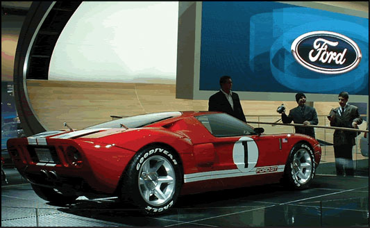
Figure 1: Ford GT at North American Auto Show in Detroit
This project, with high risk and a compressed delivery schedule,
was awarded to Apex Manufacturing in Troy Michigan, where we build
molds for the Zinc and Aluminum die-cast industry. For our CAM system,
we had been using OneCNC Mill Pro with great results because it
was easy to use and created effective cutter paths. However, when
processing some test data of the size and intricacy in the DLO,
it was evident that a few changes would make the job go more quickly.
Specifically, we needed faster code generation to enable more design,
cut, check iterations, as well as an effective way to select one
part feature to machine with assurance that others on the same surface
would not be touched. We also wanted to leverage our high speed
machining capabilities to cut the DLOs 0.060 wide 1.200 deep
B side mounting flange cavity that required a .050 ball end mill
(Figure 2).
Concurrent with the planning stages of the project, OneCNC was
preparing to release the Mill Expert version, which came to us just
as we were ready to cut.
After loading the new software, the first thing that we noticed
was that the new interface is much like the old version; menu and
wizard driven, hence no training required.
Next, we set up the post processor for our machine, and after 15
minutes we were making test cuts.
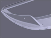
Figure 2: B side mounting flange
Now came the acid test of importing the 50 Meg data file via the
new Rhino direct import. The import was quick and the data integrity
was flawless, soon we had the part moved out of In Car Position
and into the machine coordinate system, and were ready to generate
a roughing cutter path.
Even with a .0005 tolerance, the speed of code generation was at
least five times faster than the Mill Pro version. With 4000 square
inches of mold surface to cut, the time savings was substantial.
Like in the old Mill Pro version, machined part simulation provides
a great tool for error proofing because it is created from the tool
path and not from the original cad data. As a result, the cut simulation
shows definitively what the machined surface will look like. The
simulation even shows scallops related from an excessive step over
distance. After simulating the first rough cut, some surface anomalies
were evident, which were traced back to untrimmed surfaces and holes
in the original IGES file.
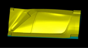
Figure 3:Rough Cut Simulation
To correct these problems, Mill Expert has surfacing tools such
as sweeping a surface along a rail curve. These were a great time
saver because we were able to make corrections without exporting
back to our design package.
The compressed delivery schedule for the project made lights out
machining imperative. As a result, verifying paths in the cad environment
became essential, and Mill Expert has even more verification tools
than the old Pro version. Features such as viewing the tool, as
it cuts, with the path laid on top of the model surface, aided in
the process. By rotating the model and tool path about in free space,
rapids, cuts, and tool changes were all verified relative to the
design surface.
This tool was especially useful when verifying how the .050 ball
end mill was going to follow the surface of the deep mounting flange
(Figure 2).
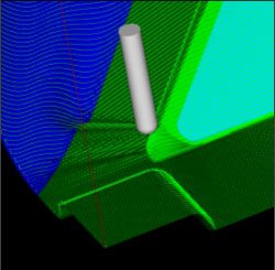
Figure 5: Viewing Tool Path
With feeds of 750 IPM and three days, we had 4 master patterns
to produce the driver and passenger side DLO for the Ford GT.
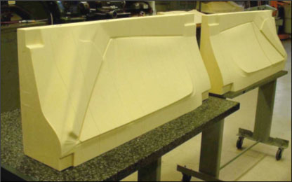
Figure 6: Left and Right A Side Master Models for the Ford GT
DLO
From the master patterns, and a plaster casting process, the finished
castings for both sides of the car were created a week later (Figure
7).
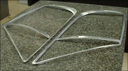
Figure 7: Finished Castings for Both Sides of the Ford GT
Figure 8 illustrates how well both detail and surface quality were
represented in the finished part.
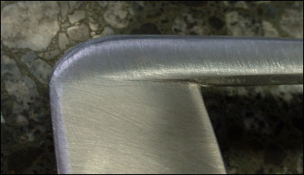
Figure 8: A Surface Detail
After painting, and fitting with window glass, the DLO was installed
during the build process at Saleen Specialty Vehicles in Troy Michigan.
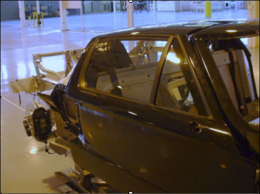
Figure 9: Ford GT During Assembly at Saleen Specialty Vehicles
Ready to be trucked to Fords 100 year celebration in Dearborn Michigan,
the GT was completed with one day to spare (Figure 10).
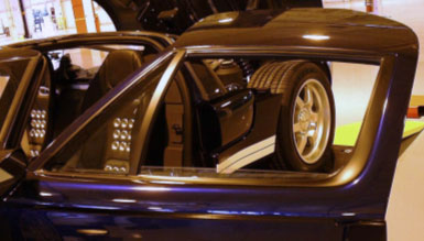
Figure 10: Finished Frame
So, when time counts call on OneCNC to do it.
|
